CAB Radio MTR10 is equipment intended primarily for voice communication in GSM-R networks (mobile communications in railway systems) between the engine driver and the traffic controller, station dispatcher or other participants. MTR10 fully complies with the requirements placed on vehicle terminal ERTMS/GSM-R in accordance with TSI CCS for Grade A equipment. With connection to analog radio it is also possible to fully communicate in RRS (Railway Radio System) networks. The equipment was designed in accordance with the proposed standard 612 of UIC (Unified Engine Driver Work station).
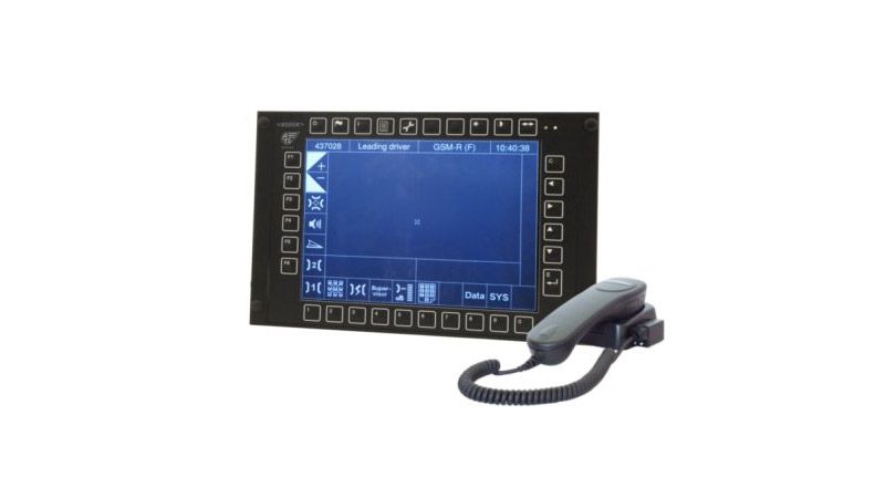
FCB30 (control box) A handset with magnetic hanger and a PTT button and speaker is connected to the control box
Power supply
24V DC, 48V DC and 110V DC
Input power
up to 250W (depending on configuration)
Coverage degree
FRB30 - IP20 FCB30 - IP54 – front panel, IP20 - Other surfaces
Antenna connectors
2x SMA connector for antenna in GSM band (900/1800MHz)
2x SMA connector for antenna GPS
1x TNC connector for GSM-R (900MHz) antenna
Communication interface
FRB30
1x RRS - connection RRS radio block
1x RS422/485 + CAN - ETCS
1x RS232 - service purposes
1x Ethernet interface - connection to FCB30
1x ethernet připojení jiných aplikací
DMI (FCB30)
Ethernet interface - connection to FRB30
2x USB
1x RS232 (authentic./service purposes)
RS422/485 + CAN (for other equipment)
I/O (2x Binary input, 2x Binary Output)
Operation in RRS system when using
interconnection with VL47 logic box VS47 unit or connection with radio block FAB20
Expansion options
data communication through data cards KN35017-2
Reader for authentication of engine driver using contact-free chip cards (Mifare/DESFire)
data interconnection with ETCS system (transmission of train number)
Dimensions (h,w,d)
FRB30 - 133 x 483 x 222mm
FCB30 - 214 x 310 x 83mm
Weight
FRB30 - 9kg
FCB30 - 3kg
Standards and authorizations
EN 50155, EIRENE FRS v8.0.0, EIRENE SRS v16.0.0, UIC 612
Description MTR10 - CAB Radio
In addition to voice communication in GSM-R networks, CAB radio MTR10 enables transmission of data in the GSM-P network via GPRS data transfers, between the train and stationary infrastructure (two-way communication). Within the framework of the RRS network, it is possible to implement duplex voice connection, identification transmission, and selective communication with the chosen party and potentially transmission of routine reports.
In the event that the train locomotive is equipped with the ETCS (Ansaldo) system (train number transmission), the FCB30 control box takes the train number from this system.
MTR10 equipment can be fitted with a reader for identification of the engine driver in the Mifare/DESFire system as well as enabling communication through the UIC cable of the vehicle.
CAB Radio MTR10 is designed as a modular system whose individual blocks are functionally interconnected:
FCB30 control panel (DMI)
FRB30 radio block
Simplex /duplex RRS (Railway Radio Systems) radio station unit
The train locomotive is usually fitted with two FCB30 control panels, whereas in practice only one of the panels is active at any one time within the vehicle. The FRB30 radio block is equipped, in the direction of the RRS system, with an interface that is the electrically equal to the existing interface of the VO47 control box, which it can replace.
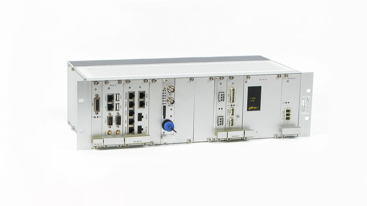
FRB30 Radio Block
The FRB30 primarily enables voice communication in the GSM-R network. It is composed of several modules that are fitted into a 19” housing. For data transmission, the FRB30 block can be expanded by a module utilizing GPRS transmission technology (support for external applications). Buttons for activation of the facing, emergency buttons, handset and speaker are connected to the radio block (in accordance with the proposal of the UIC 612 standard).
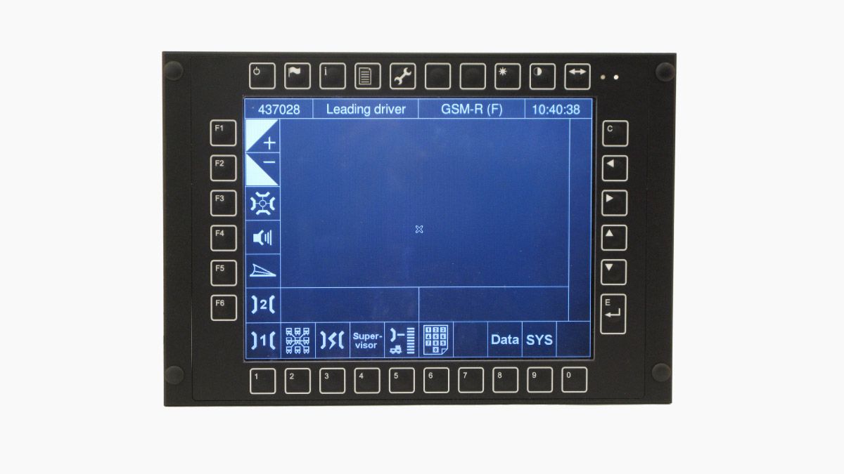
FCB30 Control Panel (DMI)
The FCB30 acts as the user interface for the engine driver for controlling the MTR10. It is fitted with a TFT LCD 10.4” graphic display with a resolution of 800x600 pixels. The front panel is equipped with a backlit, film keyboard with 32 keys and adjustable lighting intensity. Other external applications can be displayed and controlled on the display. The mechanical arrangement complies with the UIC 612-01 standard.